
Micrometer screw gauge: least count, parts, types of errors with PDF
The tool a mechanical engineer comes across almost every day is the Micrometer screw gauge along with the Vernier caliper. Hence, knowing about the micrometer screw gauge and how to use it, is important.
This is The Mechanical post and today we would be learning about the parts of a screw gauge, how to use it, formulae and calculations of micrometer, and much more.
Get your copy of the PDF on the Micrometer screw gauge at the end of this article.

What is a Micrometer screw gauge?
The Micrometer screw gauge is a measuring device that works on the principle of a screw. When the screw is rotated the spindle moves precisely back and forth to measure the workpiece.
The micrometer screw gauge is used for measuring the diameters of wires, the thickness and of a workpiece, and much more. It is widely used in the mechanical engineering field, in the tool room of workshops and metrology labs.
The micrometer has a least count of 0.01mm or 0.001cm.
Parts of micrometer screw gauge
- Frame
- Sleeve
- Anvil
- Thimble
- Spindle
- Ratchet
- Locking screw
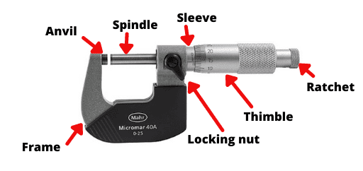
Frame
The C-shaped metal part of the screw gauge micrometer is known as the frame. It supports the anvil to the left and the sleeve & spindle to the right.
Anvil
The anvil is a small fixed part on the left end of the frame. Its face is parallel to the face of the spindle. Since it comes in contact with the workpiece it is machined to achieve a high surface finish for better precision.
Spindle
The spindle has external screw threads that help it in moving backward and forward with precise control. Usually, the spindle thread has a pitch of 0.5mm or 1mm.
Info:
Both the anvil and the spindle end have flat highly machined surfaces parallel to each other. Also, they come in contact with the workpiece every time measurement is performed.
Hence, they are highly prone to wear and thus error in measurement. That is why both spindle and anvil have Tungsten Carbide ends in order to prevent wear.
Sleeve/Barrel
A sleeve is connected to the right-hand part of the frame. The spindle can move to and fro inside it. The Main scale or the linear scale is marked on the sleeve.
Thimble
The thimble is mounted on the sleeve and it has the circular scale marked on it. The end part of the thimble has knurling on it for proper grip.
By rotating the thimble, the spindle can be controlled to and fro.
Ratchet
The ratchet of the screw gauge is used for making fine adjustments during measurement. It also prevents overtightening while measuring a workpiece.
The ratchet also makes sure that equal pressure is applied by the spindle during measurement.
Locking nut
The locking nut is used to lock the spindle from turning. This feature is useful while taking measurements it holds the scales at a fixed position to prevent error while noting down the readings.
Types of scale on micrometer screw gauge
- Main scale (linear scale)
- Circular scale
Main scale
The main scale or the linear scale is marked on the sleeve. The linear scale has markings above as well as below the line. The ones above, have markings in steps of 1mm.
Whereas the markings below the line have scales in steps of 0.5mm. So the lowest that you can measure using the Main scale of the screw gauge is 0.5mm.
Circular scale
The scale is marked on the circumference of the thimble. Usually, a micrometer screw gauge has 50 or 100 divisions on its circumference.
Fun Fact:
William Gascoigne an English astronomer was the first person to use the micrometric screw principle. He used it in a telescope for measuring the angular distance between the stars.
Source – Wikipedia
Least Count of Micrometer screw gauge
The minimum length that can be measured using a screw gauge is known as the least count of that screw gauge.
Mathematically,
Least Count of screw gauge = Pitch of screw gauge / No. of divisions on circular division
For example if, the Pitch of the screw gauge = 0.5mm
Number of divisions on circular scale = 50
∴ least count of screw gauge = 0.5 / 50 = 0.01mm
Similarly, some screw gauges have a 1mm pitch with 100 divisions on the circular scale.
∴ least count = 1 / 100 = 0.01mm Hence, the least count of micrometer screw gauge is 0.01mm or 0.0001cm.
Types of errors in screw gauge
- Positive zero error
- Negative zero error
Positive zero error
By bringing the spindle and anvil together, if the zero (0) marking on the circular scale is below the main scale line, then the zero error is termed as “Positive zero error”.
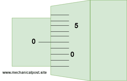
To find the amount of positive error, note down the circular scale reading (C.S.R) coinciding with the main scale reading ( M.S.R). Refer to the above fig:
Take for example the above image, here the division is coinciding with the main scale reading i.e. Circular scale division (C.S.D) = 2
Now multiply it with the least count of the screw gauge i.e 0.01mm
Positive error = C.S.D * Least count = 2 * 0.01 = + 0.02mm
(Since it is positive zero error a +ve sign is used.)
Now, whenever we measure a job with the micrometer screw gauge then we have to compensate for the +0.02mm error.
Take for instance you measured a wire with this micrometer and the diameter was found out to be 3.50mm.
Therefore, the corrected reading will be as follows:
Corrected reading = Observed reading – Zero error
∴ Corrected reading = 3.50 – (+0.02) = 3.48mm
Negative zero error
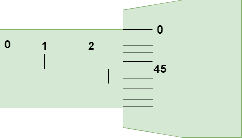
By bringing the spindle and the anvil together, such that their faces touch each other, and if the zero (0) marking on the circular scale is above the main scale line then, the zero error is known as “Negative zero error”.
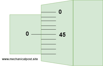
To find the amount of negative error, note down the circular scale reading (C.S.R) coinciding with the main scale reading ( M.S.R). Refer to the above fig.
Take for example the figure given above, here the division is coinciding with the main scale reading.
Circular Scale Division (C.S.D) = 45
Now multiply it with the least count of the screw gauge i.e 0.01mm
∴ Negative error
= C.S.D * Least count
= 45 * 0.01
= – 0.45mm
( Since it is Negative zero error a -ve sign is used.)
Now, whenever we measure a job with the micrometer screw gauge then we have to compensate for the +0.02mm error
Take for instance you measured a job with this micrometer and the thickness was found out to be 2.72mm.
Therefore, the corrected reading will be as follows:
Corrected reading
= Observed reading – Zero error
= 2.72 – (-0.45) = 3.17 mm
Therefore, the corrected reading will be 3.17mm
How to use a micrometer screw gauge?
Now we’ll discuss the steps that you need to follow to properly read a screw gauge.
Step 1:
Calculate the least count of the micrometer. Check whether it has zero errors. If yes, calculate how much?
Step 2:
With the help of the thimble bring back the spindle so that the workpiece can fit in.
Step 3:
Place the workpiece between the anvil and the spindle and with the help of the thimble bring the spindle to the workpiece till it touches the workpiece.
Step 4:
Now with the help of the ratchet make a fine adjustment until you hear a clicking sound. This confirms that the workpiece is gripped properly.
Step 5:
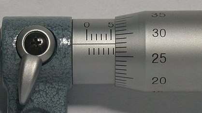
Image credits: Photograph taken by Glenn McKechnie, CC BY-SA 3.0, via Wikimedia Commons
Note down the Main Scale Reading (M.S.R). We will take for example the reading shown in the above picture thus, in this case, M.S.R = 5.5mm.
Step 6:
Now note the Circular Scale Division (C.S.D) coinciding with the main scale reading. In this case, it’s the 28th division.
Step 7:
Multiply the Circular Scale Division (C.S.D) with the least count of the screw gauge to get the Circular Scale Reading (C.S.R).
In this case, it will be:
C.S.R = 0.01*28 = 0.028
Step 8:
Now add the main scale reading as well as the circular scale reading to get the Observed Reading (O.R).
Therefore, in our case it will be as follows:
O.R = M.S.R + C.S.R = 5.5 + 0.028 ∴ O.R = 5.78mm
Step 9:
If the micrometer has zero error then this step has to be applied. If not, then 5.78mm would be the final reading.
To get the correct reading, we must compensate for the zero error of the screw gauge.
In this case, our micrometer has a zero error of – 0.02 (i.e negative zero error)
∴ Corrected Reading = O.R – zero error = 5.78 – (-0.02) = 5.80mm
Hence, the final reading would be 5.80mm
Advantages of micrometer screw gauge
- Micrometers are more accurate as they have a least count of 0.01mm.
- Screw gauges come in different types based on their application.
- They are durable and have a good working life.
- They are widely used in fieldwork to get quick and precise readings.
Disadvantages of micrometer screw gauge
- Micrometer screw gauges have a limited range of measurement.
- As they come with full metal construction, they are expensive.
- For different types of uses different micrometers are required.
Practice questions on Micrometer screw gauge
Q1: Given below is the position of the scales on a micrometer while measuring the diameter of a steel rod. The pitch of the screw is 0.5mm and the circular scale has 50 divisions on it. If the micrometer has a positive zero error of +0.03mm, find the final value of the diameter.

Pitch of screw = 0.5mm No of division on circular scale (C.S.D) = 50
∴ Least Count = Pitch of screw / No of division on circular scale = 0.5 / 50 = 0.01 mm
From the above figure, Main Scale Reading (M.S.R) = 3.5 mm
Circular Scale Division (C.S.D) = 2
∴ Circular Scale Reading (C.S.R) = C.S.D * least count = 2 * 0.01 = 0.02
∴ Observed Reading (O.R) = M.S.R + C.S.R = 3.5 + 0.02 = 3.52 mm
∴ Corrected Reading = O.R – zero error = 3.52 – (+0.03) = 3.49 mm
Hence, the diameter of the steel rod is 3.49 mm.
Q2: From the figure given below, calculate the final reading of the micrometer. Take the value of least count as 0.01 mm. There is no zero error in the micrometer screw gauge.
Solution:
From the picture above, Main Scale Reading (M.S.R) = 2.5 mm
Circular Scale Division (C.S.D) = 45
Least Count = 0.01 mm
∴ Circular Scale Reading (C.S.R)
= C.S.D * least count
= 45 * 0.01 = 0.45
∴ Observed Reading (O.R) = M.S.R + C.S.R = 2.5 + 0.45 = 2.95 mm
Since there is no zero error the final reading will be 2.95 mm
Want to buy a screw gauge? Here are some good options
Looking to buy a micrometer for yourself or thinking to gift it to someone? We get you covered. The micrometer screw gauge would be a wonderful gifting idea for a mechanical engineer be it for a student or a professional.
Here are the 2 Micrometer screw gauges to buy:
- Mitutoyo 103-129 Outside Micrometer
- Mitutoyo 293-821-30 Digimatic Digital Micrometer
#1 Mitutoyo 103-129 Outside Micrometer

Mitutoyo is a world-renowned Japanese brand that specializes in measuring instruments. They have years of experience in producing high-quality products.
This is an outside micrometer by Mitutoyo with a measuring range of 0-25mm and a ratchet mechanism for fine adjustments.
This is a widely used micrometer and even I have used it and the micrometer works very well!
If you are looking for a mechanical micrometer on a good budget then this is the one to go for.
#2 Mitutoyo 293-821-30 Digimatic Digital Micrometer

This is a digital micrometer screw gauge which makes it easy and very quick to take a reading. No calculation and nothing. Just switch it ON and hold the workpiece between the anvil and the spindle and that’s it.
The reading will be directly displayed on the LCD screen. This digital screw gauge micrometer by Mitutoyo is the best for its budget. It comes in a range of 0-25mm and is battery-operated.
Along with the digital LCD, you get the conventional scales marked on it which is a good feature especially when the battery dies out and you have to urgently take a reading. So you can use this micrometer in digital as well as normal mode.
If you click on any link on mehanicalpost.site and decide to buy it, we may earn from qualifying purchases. Mechanialpost.site is a participant in the Amazon Services LLC Associates Program, an affiliate advertising program designed to provide a means for sites to earn advertising fees by advertising and linking to Amazon.com and any other website that may be affiliated with Amazon Service LLC Associates program. Learn more
This brings us to the end of the article. Loved reading or found it helpful? Let us know in the comments.
Also, do share this article with your fellow engineers. We’ll be back with another interesting article till then keep learning!


![37 Must Have Workshop Tools & Their Uses with [PDF & Images]](https://mechanicalpost.site/wp-content/uploads/2023/07/tool-stoarge.webp)


it was very helpful. Great job!
We are extremely pleased to hear it 🙂