Types of couplings: its uses, advantages and limitations with PDF
Greetings! Today at The Mechanical post we’ll see the types of shaft couplings, their construction, assembly, advantages, disadvantages and applications.
Also, you can download the PDF on Types of Couplings at the end of the article. So let’s get started.

What is coupling?
A coupling is a type of connector which connects two shafts together and enables torque and power transmission through it. Shafts are usually available 7 metres in length for easy handling and transportation. Therefore, when power is to be transmitted at a greater distance more than 7 metres, more than one shaft is needed.
This is because very long shafts tend to bend due to their own weight. This can cause vibrations, noise and eventually the shaft might break. To prevent this, shafts are connected by the coupling which connects two shafts together and helps to transmit power.
Functions of coupling
- Must disconnect easily for repairs or maintenance.
- It must be easy to connect the shafts and must hold them properly.
- Coupling must be able to connect shaft units, which are manufactured separately. For e.g. A motor shaft and a generator shaft.
- To compensate for misalignment of connected shafts.
- To introduce mechanical flexibility ( such as in case of flexible coupling ).
- To reduce and absorb transmission of shock loads from one shaft to another shaft.
- To provide protection against overloads.
- To change the vibration characteristics of rotating members, whenever required.
Classification of Couplings:
Couplings are broadly classified into 2 categories.
1. Rigid coupling.
2. Flexible couplings.
1. Rigid coupling
- It is used to connect two shafts, which are in perfect alignment.
- It consists of two flanges with hubs, one keyed to the driving shaft and other two the driven shaft. Two flanges are bolted together.
Applications of rigid coupling:
- When the required length of the shaft is too long and is difficult to manufacture such long shaft, then two or more shafts of suitable length are connected with the help of sleeve or muff coupling.
- For motor-pump sets, motor-gear box sets etc.
Types of rigid coupling:
- Sleeve or muff coupling.
- A split muff or clamp coupling.
- Flang coupling.

2. Flexible coupling
- It is used to connect two shafts having both lateral and angular misalignment.
- Its construction is similar to a rigid coupling, except that, a flexible element, such as rubber bush is inserted between the coupled parts.
- Rubber bush is provided with brass lining to avoid excessive wear. These bushes absorb the misalignment between the shaft.
Types of flexible coupling shaft:
- Bushed pin-type coupling.
- Universal coupling.
- Oldham coupling.
What is the difference between rigid coupling and flexible coupling?
A rigid coupling is used to connect shafts with perfect alignment while flexible couplings permit a small amount of misalignment between the shafts. A flexible coupling is expensive as compared to rigid coupling. Also, the flexible coupling can absorb shocks and vibrations whereas a rigid coupling cannot.
Now let’s talk in detail about each coupling starting off with Sleeve or muff coupling.
The following are the different types of coupling:
1. Sleeve or muff coupling
Sleeve or muff coupling consists of a sleeve or muff which is a type of hollow cylinder. The internal diameter of the muff is equal to the external diameter of the shaft. The two shafts which are to be coupled have keyways built into them. A gib headed key is used to connect the shafts to the muff.

Assembly of sleeve or muff coupling
The shafts are taken and the keys are slid over it. Both the shafts along with the keys are then fitted into the sleeve. In this way, the sleeve or muff coupling is assembled. This type of coupling is used for small diameter shafts.
Advantages of muff coupling
- Its the simplest type of coupling with only 2 parts i.e muff and key.
- It is compact in size.
- It has no projecting parts which make it safe for usage.
- It is economical.
Disadvantages of sleeve/muff coupling
- The main disadvantage of a rigid coupling is that it cannot tolerate any misalignment in the axes of the shafts.
- It is difficult to assemble or dismantle as the sleeve has to be shifted over a shaft or shaft ends.
- It is not able to absorb shocks or vibrations during power delivery.
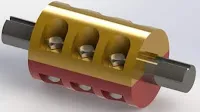
2. Split-muff or clamp coupling
This coupling is similar to the sleeve coupling above. You can say that it is the upgraded version of the muff coupling. The main difference between the two is that the muff or sleeve is split into two halves. Unlike in the above coupling, which has the sleeve as a hollow cylinder, the clamp coupling has the sleeve split into 2 parts which are held together by nuts and bolts.
This provides strength to the coupling as well as making it easier to assemble and dismantle as compared to the sleeve or muff coupling.
Advantages of clamp coupling
- Coupling’s strength is more as compared to muff coupling.
- It can transmit more torque than the muff coupling.
- It can be easily assembled and dismantled.
- It is small in size diametrically.
Disadvantages of clamp coupling
- Its cost is more as compared to muff coupling due to more parts.
- As it contains nuts and bolts, it becomes unsafe. Thus protection must be provided.
- It cannot absorb shocks and vibrations.
3. Flange coupling (Protected type)
The flange coupling is extensively used type of coupling. It consists of a hub inside which the shaft is fitted with the help of the key. The two flanges have diametric holes drilled into them for the bolt to pass. These bolts are used to connect both the flanges and the nuts are used to secure them.
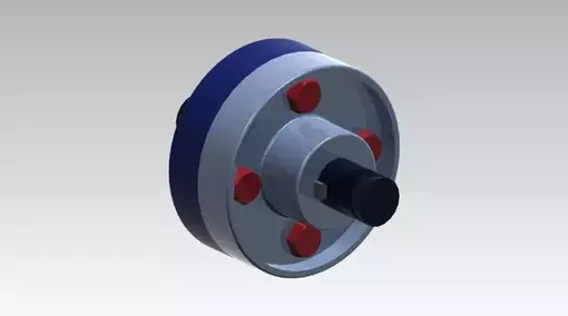
Thus both the flanges are connected resulting in connection of the shaft. They usually have 3,4 or 6 nuts and bolts depending upon the size of the shaft.
Since the flange coupling has nuts and bolts it is not safe, as due to centrifugal force it might loosen up and might hit anything around it. For this purpose, a protected type of flange coupling is used. As shown in the figure, a little part of the flange is extruded such that it covers up the nut and bolt.
Must check out: Screw thread terminology and types of screw threads
Advantages of flange coupling
- Simple in construction
- Is capable of transmitting high torque as compared to muff coupling.
- Is suitable for high speed.
- Easy to assemble and dismantle.
Disadvantages of Flange coupling
- It cannot tolerate misalignment, the shafts need to be perfectly aligned.
- It cannot absorb or withstand shocks or vibrations.
4. Gear coupling
The Gear coupling is similar to that of the Flange coupling but this one is a flexible coupling. The gear coupling permits parallel misalignment of 0.25 to 0.5 mm as well as angular misalignment of 2 degrees.
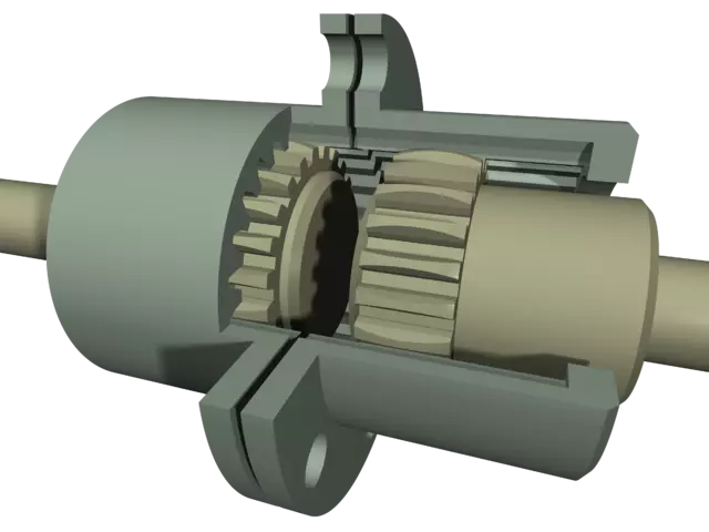
The gear coupling consists of two hubs that have external gear teeth cut on their circumference as well as two flanges (with internal gear teeth). The flanges are held together with the help of nuts and bolts.
The power is transmitted from the driver hub to the flange as they are in mesh with each other. Then from the 1st flange the power is transmitted to the other flange as they are connected via nuts and bolts. Now as the other flange rotates, it causes the driven hub to rotate as the 2nd flange and the driven hub are in mesh with each other. This is how gear coupling works.
Related article: Different types of gears, their advantages, uses and much more.
Advantages of gear coupling
- Gear coupling is capable of transmitting high amount torque
- They have a long life
- Gear coupling is reliable
Disadvantages of gear coupling
- It requires lubrication after regular time period.
- Improper lubrication result in increased heat and wear
- Gear couplings are subjected to backlash error.
Applications of gear coupling
Gear couplings have applications in large industrial machinery like large pumps, blowers, mixers as well as in steel and wire mills.
5. Jaw coupling
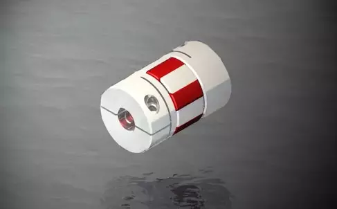
A jaw coupling is a type of flexible coupling that permits some amount of angular misalignment between the shafts. The coupling consists of 2 hubs with interlocking jaws with a soft elastic material called the “spider” placed in between the jaws.
It is the spider that enables the jaw coupling to allow angular misalignment between the two shafts. Another function of the spider is to absorb the shocks and vibrations during transmission, thus protecting other components from damage.
The spider comes in a variety of hardness levels, which allows the user to select the proper setup according to the application. A soft spider translates to improved vibration dampening and angular misalignment capabilities. On the other hand a hard spider results in better torque transmission.
Jaw couplings are “fail-safe” couplings as they last a long time as compared to the other types of couplings mentioned above.
Advantages of Jaw coupling
- Jaw couplings are easy to assemble/dismantle
- Low maintenance costs
- Spiders can be easily replaced
- Can handle angular misalignment between shafts
- Does not require lubrication
Limitations of Jaw coupling
- Jaw couplings can tolerate only some level of misalignment
- It is limited to a particular range of operating temperature
- There is problem of backlash and it increases with time.
Applications of jaw coupling
The applications of jaw couplings include:
- Different types of Compressors
- Pumps
- Blowers
- Mixers
You might also like to read:
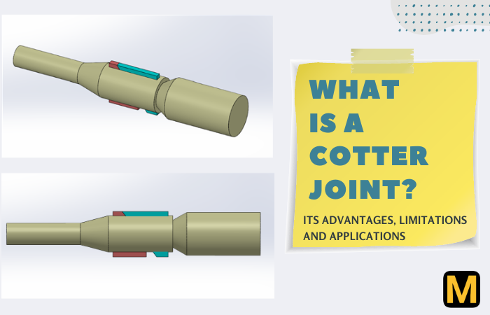
- What is a cotter joint and its different types?
- 9 best laptops to buy for mechanical engineering students in India
- Python for Mechanical engineers: Why should you learn?
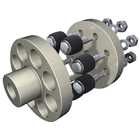
6. Bush pin type flexible coupling
The bush pin type flexible coupling is an alteration of the flange coupling mentioned above. The Bush coupling has rubber bush and pins and nuts in place of nuts and bolts in the flange coupling. The rubber bush provides flexibility to the flange coupling.
The flexible flange coupling consists of two flanges one keyed to the input shaft and the other keyed to the output shaft. The two flanges are connected together using 4 to 6 bush and pins depending upon the diameter of the shaft.
The pins are fixed to the flange with the help of a nut. The rubber bush used is provided with a brass lining at its inner surface to avoid wear of the rubber bush. The flange hub is connected to the shaft with the help of a key.
Generally, a clearance of 5 mm is kept between the two flanges of the coupling. First, there is no rigid connection between the two flanges and that power transmission takes place through the medium of rubber bushes. Due to this flexibility is induced in the coupling.
Advantages of bush pin type flexible coupling
- Its construction is simple
- It absorbs shock and vibration during power transmission.
- This type of coupling can handle misalignment of 0.5 mm laterally and 1.5 degree angular misalignment.
Disadvantages of Bush pin type flexible coupling
- It is not economical i.e. its cost is high due to more components.
- Radial space required by the coupling is more as compared to other couplings.
7. Oldham’s coupling
The Oldham coupling is another type of flexible coupling designed for shafts with parallel misalignment. It was invented by John Oldham in Ireland in the year 1821. Jaw couplings are being replaced by Oldham’s coupling. The Oldham’s coupling is an inversion of double slider crank chain mechanism.
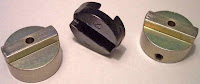
The coupling has three components i.e. two flanges and a centre disc. The 2 flanges are connected to the shafts with the help of keys. The flanges have inner grooves made into them as shown in the figure. Whereas, the centre disc has projections made onto it.
These projections fit into the grooves made into the flanges. Thus, the centre disc is sandwiched between the 2 flanges, also the centre disc is free to slide in the grooves as shown below.
The flanges are made up of stainless steel or aluminium alloy. Whereas, the centre disc is made up of polymers or plastics. This reduces the friction between the flange and the centre disc while sliding. Also, it adds flexibility to the coupling.
Advantages of Oldham’s coupling
- Its size is compact.
- Easy to assemble.
- In case of excessive load, the centre disc will be the one to break first. Thus preventing the failure of other important machine components.
- The centre disc can be replaced easily and is inexpensive.
- It can effectively absorb shocks and vibrations.
- It can tolerate misalignment in shafts.
- Due to the presence of plastic centre disc, the coupling becomes electrically insulated.
- It is economical.
Disadvantages of Oldham’s coupling
- It cannot tolerate angular misalignment.
- It cannot tolerate high torque.
- Due to the sliding movement, the centre disc is subjected to wear, thus after a particular time period, it has to be replaced.
Applications of Oldham’s coupling
- It is used in a stepper motor.
- In robotics.
- Servo motor applications.
- In printers and xerox machines.
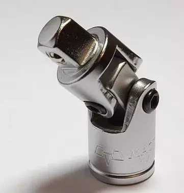
8. Universal coupling
The universal coupling is one of the most versatile couplings when it comes to connecting shafts at an angle. It can be used for shafts at 90 degrees to each other. It allows efficient transmission of power and torque between misaligned shafts at any angle, thus the name universal coupling. The propeller shaft used in Automobiles is one of the most well-known application of Universal coupling.
Well, we have a detailed article on Universal coupling, do check that one out for more details.
9. Fluid Coupling
The fluid coupling is another type of flexible coupling. It is also known as ‘Hydraulic Coupling‘. In this coupling the rotational motion is transferred from one shaft to another with the help of transmission fluid between them.
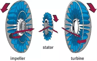
The fluid coupling has 4 main components i.e the Impeller, stator, turbine and a hydraulic fluid. The impeller is attached to the driver shaft whereas the turbine is attached to the driven shaft. In between them, a stator and a hydraulic fluid is present.
So when the impeller rotates due to the driver shaft, it causes the hydraulic oil to low radially outwards. Thus the impeller acts like a pump. Now the high velocity fluid after passing through the impeller is guided by the stator such that it strikes the blades of the turbine at a certain angle.
The fluid passing through the stator and after striking the blades of the turbine causes it to rotate and thus, the shaft attached to the turbine rotates.
So the transfer of energy is as follows:
Mechanical energy (Impeller) ➡ Kinetic energy of Hydraulic fluid ➡ Mechanical energy (Turbine)
Advantages of Fluid Coupling
- Fluid coupling is almost free from vibrations.
- Transmission is smooth
- Can be fitted vertically or horizontally
- Less noise while operating
Limitations of fluid coupling
- There is a lag between driver and driven shaft speeds initially.
- It is expensive as compared to other couplings.
- There is always some amount of energy loss.
- There are chances of oil spillage if not maintained well.
- Oil leakage can make the surroundings messy.
Applications of Fluid coupling
- Fluid coupling is used in automobile transmission
- Locomotives
- Marine propulsion
Requirements of a good coupling:
- Coupling should be easy to assemble and dismantle.
- Coupling should be able to transmit 100% power from one shaft to the other shaft without any power losses.
- Coupling should hold the shafts in perfect alignment.
- Coupling should be able to absorb and reduce shock and vibration when transmitting power from one shaft to another.
- Coupling should not have projected parts or have a minimum number of projected parts.
Factors to be considered while selecting a coupling:
- Misalignment of the shaft.
- Operating conditions.
- Operating torque and speed of shafts.
- Protections against overload.
- Durability and reliability.
- Cyclic operation.
- The direction of rotation.
That’s all about Types of couplings. Like the article? Do let us know in the comments or on our Facebook page @TheMechanicalpost
We’ll be back soon with another interesting article till then Keep learning and read The Mechanical post!

![37 Must Have Workshop Tools & Their Uses with [PDF & Images]](https://mechanicalpost.site/wp-content/uploads/2023/07/tool-stoarge.webp)